How to use
Panorama Tools & PTGui to produce a printable panorama
This is a step-by-step guide to
making a printable panorama from images taken with a camera having a standard
rectilinear lens (i.e. not a fish-eye or super wide-angle). In my examples,
I have used a hand held Canon D60 with a 20mm lens (32mm equivalent focal length).
Helmut Dersch's Panorama Tools is a very versatile product but can be offputting
at first sight. However, gui front end interface programs such as PTGui by Joost Nieuwenhuijse
has transformed its usability, and by following these instructions, there's
no reason why you should not produce a panorama at your very first attempt.
Don't be put off!
Note that I have not set out to
describe every option and feature of PTGui in this tutorial. For example,
there are useful extra programs like Enblend and Autopano that can help to speed
things up by introducing a degree of automation into the process. However,
I think it is important to learn how to do things manually in the first instance
in order to gain a proper understanding of Panorama Tools.
CONTENTS
INSTALLING
THE SOFTWARE
Download PTGui and
a version of Panorama Tools from http://www.ptgui.com . I've used PTGui V4.1 in the examples here. (PC only - no MAC version, but PTMac is similar).
Photoshop (or a Photoshop
compatible plug-in host) running under 32bit-Windows is required for editing
layered files (.psd) output by the stitcher but is not used in the stitching
process itself.
For the impatient, a quickstart
pack that includes sample images, PTGui project file and very detailed step-by-step
instructions, can be downloaded from: http://www.johnhpanos.com/quickstart.zip (330K)
TAKING THE PHOTOGRAPHS
Photographs for a panorama are usually
(but not necessarily) taken in portrait mode at minimum zoom setting. Portrait
mode will give the panorama more height to offset the letter-box format, and
will also result in more image pixels and higher resolution. Use manual exposure
or the auto exposure lock feature, if available, to ensure the same exposure
for each picture. Also ensure the same white balance setting by selecting sunny
or cloudy, say, rather than auto. For your first panorama, just take three to five pictures
and overlap each picture by about 30%. If possible, use a tripod. If not, keep
the camera as level as you can, i.e. pointing at right angles to the axis of
rotation. (NB. Pano Tools will handle a tilted camera quite happily; just keep
it level for your first panorama). Ideally, the camera lens should be positioned
over the pivot to avoid parallax errors, but this is not a major concern when
photographing distant landscapes.
Note: these images are supplied
in the quickstart pack mentioned above.
PREPROCESSING THE IMAGE FILES (optional)
While it is not a requirement to
perform any processing of the images to prepare them for stitching, it can save
time later on if some image defects are dealt with here. In particular, if there
is noticeable vignetting present (darkening of the corners), it is best to correct
this in Photoshop either in the RAW image converter or using the PTLens plugin (see
links). Slight vignetting can also be readily corrected with the
Panorama Tools Correct plugin, using the radial luminance option. (There
is an option on the Source Images screen in PTGui to facilitate this). This will help with the
blending of images at the seams. It also makes life a bit easier if
the images are rotated into an upright position if appropriate. However, none of this is necessary for your first
panorama.
RUNNING THE GUI INTERFACE
Run the free-standing
program ptgui.exe.
Source Images
Tab
Click Add and browse/select your
image files. They will be entered into the display sorted into numerical order
with the yaw, pitch and roll parameters set to 0 by default.
Lens Settings
tab
Set the fields as shown here:
It is important to have a reasonably
accurate value specified for the horizontal angular field of view of your camera
lens (HFOV). This should be specified to match the orientation of the images
(landscape or portrait) as they are
to be presented to PTGui. In this
case, the photos were taken in portrait format and supplied to PTGui after rotation. Details of a simple method of measuring the HFOV
is detailed in Measuring
HFOV , but an easier option is to enter
the 35mm equivalent focal length, and let PTGui work out the HFOV for you. The
specifications of digital cameras will usually give the 35mm equivalent
of the lens e.g. 38mm-105mm for a zoom lens. If you are using
this lens in the widest angle position, then the focal length will
be 38mm. Yet another way of finding the FOV is to make use of the
camera data recorded in the image file. This is known as Exif data.
Clicking on the Exif button will check to see if there is exif data
stored in the file and offer to make use of it.
a,b
and c are used to correct barrel distortion. Most lenses can be corrected
with a suitable value for the b parameter alone. A value can be worked
out by following the calibration instructions in Calibrating the camera lens . Alternatively, you can get the optimizer to work out
a value by trial and error, which is what we shall do here.
Panorama
Settings tab
Set the Projection to be
Cylindrical (for wide angle panoramas). (See note on projections ).
The Field of View parameters define
the width and height of the output image area. We don't need to enter
any values here as we will use the Panorama Editor window to size the output
area to fit around the panorama image. However, for 360x180 panoramas,
you might as well enter those numbers here. Note that the Panorama Editor window
is scaled to display exactly this field of view, and what you see in that window
is what you will see in your finished panorama. So if the values specified here
are too large, you will see blank space around your image. Conversely, if the
values are too small, your final image will be cropped. The panorama will not
necessarily be centred vertically in the window, however. If the camera was
tilted a little upwards when the pictures were taken, you should expect the
image in the window to be shifted upwards. Understand that the centre of the
window represents 0 degrees of yaw and 0 degrees of pitch. If the horizon is
visible in the panorama, it should be positioned exactly across the centre of
the window. It will be in this position only if the correct angle of pitch is
specified in the Image Parameters tab. Fortunately, there is a way of getting
the optimizer to work out this angle automatically (see the links for the tutorial
on straightening horizons). If you have kept the camera level when taking your
pictures for this exercise, this is all of academic interest and can be ignored
(but not forgotten) for the moment .
Image Parameters tab
Enter some rough
values for the angles of yaw for the images: -30,-10,10,30 degrees. (Alternatively, you can drag the images into rough positions via
the Panorama Editor window). These
are very rough estimates of the horizontal angular positions of the camera.
Its not essential to do this, but it gives the Optimiser
a good position to start from. For very wide panoramas (>180 degrees)
odd things can sometimes happen to the layout of the images if you don't do
this. Always do it for 360 degree panoramas: use the Fill Yaw
button. If the images were taken in portrait
format and have not been rotated by any preprocessing of the images, enter roll values to rotate each image: 90 for clockwise
rotation and -90 for counter-clockwise rotation.
Control
Points tab
Select each pair of
neighbouring images (0 and 1, 1 and 2, 2 and 3 etc) in turn and set 4 or 5 pairs
of control points to mark corresponding features in the two images in the area
where they overlap. (Pull the horizontal scroll bars in to the centre to see
the overlapped areas). If you have rotated the images by applying 90 degrees
of roll, it will be helpful to rotate the images here by selecting 90 in the
Rotate pull-down menus. This has no effect on the stitching - it's just more
convenient to view the images in their natural orientation. Simply click on
the identical feature in each of the two windows. Spread the points widely -
vertically, if possible. In the case of hand held panoramas, set control points
on distant features in preference to nearby objects, to minimise the effects
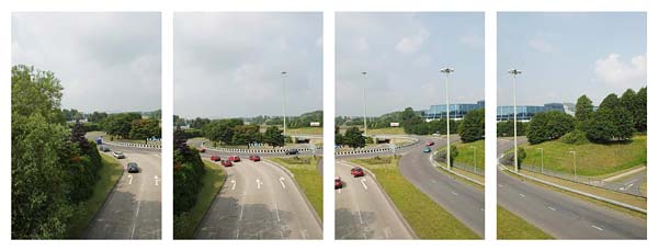
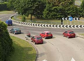
of parallax errors. (I deliberately took these pictures from a pedestrian
bridge high over the road so that there would be no close features in the foreground
to cause parallax complications in this exercise!)
Optimizer
tab
The optimizer will work out the
optimum values of yaw, pitch, roll and lens parameters to align the control
points in the images as accurately as possible. After clicking on the Optimizer
tab, select "Advanced".
Check the boxes as
shown below (image 1 is to be anchored, and the optimizer will be allowed to move
all the other images around it for best fit).
You should only optimize
up to the same number of parameters as there are pairs of control points defined
for each join. As you have four control points, you can optimize yaw,
pitch and roll together with lens parameter b. Tip - Even with more control points, it is
best to avoid optimizing too many parameters at the same time. Doing a number
of runs with only one or two parameters often seems to work better and is quicker.
E.g. First do yaw only, then yaw and pitch, then pitch and roll, then yaw and
lens parameter b, and then yaw pitch and roll again . Do not optimize Lens Field of View, except for 360 degree panoramas. If you
do, it may attempt to shrink the lens HFOV to 0 degrees (as this gives the best match of the control
points since they are all in one place!).
Click the run button.
The optimizer may take a few seconds to run and then a report on the run will
be displayed.
If it says
"bad", then you should display the list of control points and examine
any with a poor "fit". This may be due to placing control points on
features which are not actually the same, or maybe the chosen feature moved
between shots. Highlight the point in the table and then use the Goto button
to check it, and either adjust it or delete it.
Then re-optimize
Now go to the Panorama
Editor window and use the two red buttons to (a) centre the panorama in the
output area and then (b) fit the output area to the panorama.
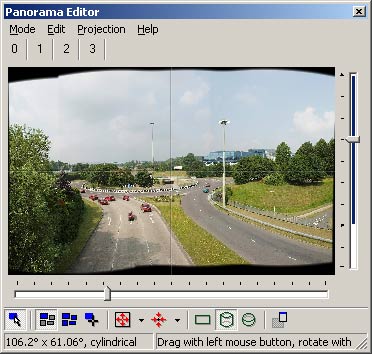
Examine the Panorama
Editor window for a good fit within the output area. You can alter the
position of the sliders to crop the image if you wish. The projection
can be switched by clicking the 3 buttons on the right.
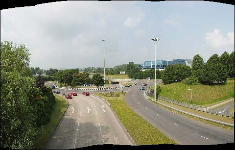
Preview
tab
For many purposes,
the Panorama Editor window provides an adequate preview of the final panorama.
Additionally, the Preview option is available to do a quick stitch at higher
quality that will give a better idea of how the final stitch will look. You
need to run Tools->Options to specify the program you want to use as your
preview viewer for cylindrical and rectilinear formats. Windows Explorer
is a good choice.
If the camera was
not kept level when taking the pictures, the panorama might show a tilt to left
or right (as here). This can be corrected by making adjustments to the roll
parameter (in the Image Parameters tab) of just the anchored image and running
the optimizer again. Remember that this image is fixed, and the other images
will be repositioned around it when you re-run the optimizer. You can also use
the Panorama Editor window to rotate the whole panorama and shift it up
or down. (The horizon should generally be positioned
half way down the ouput area for it to be rendered flat). Very accurate
leveling of horizons and correction of converging verticals can be done with
the Optimizer using special control point alignment modes, and this is dealt
with in the straightening horizons tutorial listed in the links.
Tip: The
centering button in the Panorama Editor window has options to centre both
vertically and horizontally, or just horizontally or vertically. The proper alignment of the horizon
and vertical features is achieved by altering the position of the panorama in
the output area. Centering the image vertically after doing this is
likely to destroy this alignment so vertical centering should not generally be performed in the final
stages.
Create Panorama
(At last!)
Enter a value for
the width of the panorama (the height will be scaled to match) or click on the
"Set Optimum Size" button, which will give an output image resolution similar to that of
the input images.
Select the
file format as Photoshop with feather (.psd) and browse to a folder and enter
an output file name. This will give a layered file so that problems caused by
moving cars can be corrected by editing the layers.
At this point it is
worth saving your project so do File->Save before embarking on the final
step The script will be filed with a .pts extension (a text
file).
Click on the Create Panorama button.The stitching of a large project can take quite a time, depending on the speed of your PC, so
you may sometimes want to find something else to do while this is in progress.
Tip - If you double the output image width
and height, the stitching takes approximately four times as long. It is therefore
an advantage to do trial stitches with a relatively small output image until
you are happy with it before doing the final stitch at full size. The Preview tab provides a convenient way to do these
trial stitches at a smaller size.
THE
OUTPUT FILE
The format chosen
is a Photoshop PSD file with feathered layer masks. This will allow you to adjust the
joins in Photoshop with a black/white paintbrush where there happen to be double
images caused by object movement, parallax etc. Also, if there are differences
in brightness between images, then the individual images can be adjusted to
improve the match. (See the section "Tidying the output image" below).
Tip - If there are any bad double images visible
on prominent features, you should consider going back and reassigning control
points or adding new ones. With the knowledge of where the seams have been placed,
you can assign the control points with advantage on or near the seams.
TIDYING UP THE OUTPUT IMAGE
This section is for
those who might not be familiar with editing techniques involving layer masks.
In the example above, the output file format specified was a PSD file with feathered layer
masks. An ordinary jpeg file could have been chosen, but the stitching in panoramas
is rarely 100% perfect and by outputing a PSD file, you do have the opportunity
of easily correcting/disguising any alignment errors that might be visible.
 When you open the file in
Photoshop, you will see the black and white mask thumbnails on each of the layers
in the layers palette. The masks control the transparency of the pixels in each image. If you have a double image, say, at a join, identify
the two layers involved by clicking the eye symbols to switch layers on and
off, or ctrl/right click in the overlap area. Set the active layer to be the
upper layer of the two with the problem, click on that layer's mask thumbnail to highlight it and switch into mask editing mode.
(In earlier versions of Photoshop, an additional column showing a brush or circle indicates image or mask editing mode).
When you open the file in
Photoshop, you will see the black and white mask thumbnails on each of the layers
in the layers palette. The masks control the transparency of the pixels in each image. If you have a double image, say, at a join, identify
the two layers involved by clicking the eye symbols to switch layers on and
off, or ctrl/right click in the overlap area. Set the active layer to be the
upper layer of the two with the problem, click on that layer's mask thumbnail to highlight it and switch into mask editing mode.
(In earlier versions of Photoshop, an additional column showing a brush or circle indicates image or mask editing mode).
Select the paintbrush
tool and make sure that the foreground and background colours are set to pure
black and white. Generally it will be best to work with a soft brush shape (with
a fuzzy edge). By painting on the selected layer with a black brush, you erase
the layer. By painting with a white brush you will replace the image. In this
way, you can control the merging of the two layers at the join very precisely.
If you make a mistake, just change the paintbrush colour and paint back over
the error. Tip - click on the pair of arrows next to
the foreground and background squares in the toolbox palette to flip between
painting white and black.
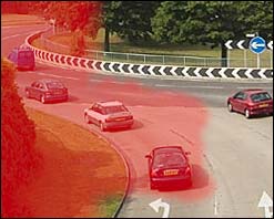
When you are editing
a mask, you may sometimes find it helpful to make it visible as a red overlay.
Just toggle the red mask on and off by pressing the backslash key (\).
To switch out of mask
editing mode, click on the image thumbnail to the left of the active layer's
mask thumbnail.
Here's a stitching error
caused by traffic movement in the overlap between image 0 and 1:
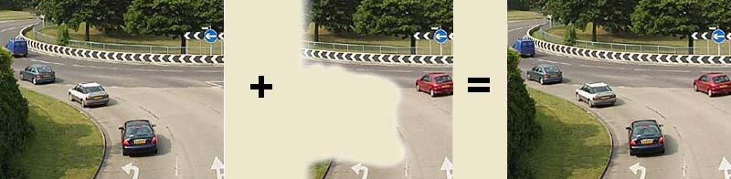
This can be corrected
by adjusting the layer mask of image 1 like this:
So that:
PUTTING THINGS INTO PERSPECTIVE
Newcomers to Panorama
Tools are often concerned about the acres of blank space that sometimes surround
the output image. If you understand why the blank space is there, you will cease
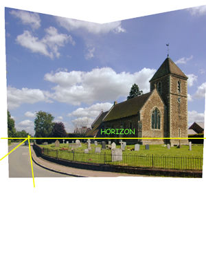
to worry and just crop it away. Look at this output, which is a rectilinear
stitch of two portrait shots, side by side. The camera was rotated about a vertical
axis but tilted upwards by about 11 degrees for each. (Who said you must keep
the camera level?).
In the same way that
a vertical line at the centre of the width of the image area represents 0 degrees
of yaw, a horizontal line half way down the image area represents 0 degrees
of pitch. This is where the horizon lies (assuming a vertical axis of rotation).
Because the camera was deliberately angled upwards to get the whole of the building
in, the horizon naturally is near the bottom of the camera frame. The perspectives
will all come out right when the horizon in the panorama is aligned with the
centre of the stitched image area. The horizon (if visible) should then also
be straight.
So, if you take a
hand held shot like this one, and you don't know how much you angled the camera
upwards, you can do trial stitches with different pitch values until you get
the horizon centrally positioned. However, there's a better and quicker method
provided
by PTGui. Use the "Set Centre Point" on the Panorama Editor window
- just click on where you think the horizon is. The perspectives should then
automatically be correct, as they are here. You may have to guess the position
of the horizon if it is not actually visible. Here I was fortunate to have a
level, straight road nicely converging to a vanshing point indicated by the
yellow lines. The vanishing point lies on the horizon. (See links for more detailed
guidance on levelling horizons).
CALIBRATING THE CAMERA LENS
Many zoom lenses exhibit pronounced
barrel distortion, which will need to be removed in order that stitching can
be successful. This can be done either during the preprocessing or left until
later when running PTGui. Usually it's more convenient to do the latter and
most people just leave it to the optimizer to work out the correction. Or,
you may like to investigate PTLens (from www.epaperpress.com
), which generates lens parameters for popular cameras and lenses.
I used to use a Photoshop batch run to
rotate and de-barrel all the images, and also correct for minor vignetting. These
days, I do the image rotation and vignetting and chromatic aberration correction
all within Photoshop's RAW conversion plugin. Once you are thoroughly
familiar with Panorama Tools, you will naturally establish your own workflow
that suits you. If you want to remove barrel distortion in an image
using the Panorama Tools plugins in Photoshop, you carry out the following procedure:
In Photoshop, select Filter->Panorama
Tools->Correct
Then tick Radial Shift and click on options.
Set the parameters for radial shift as follows:
a = 0
b = -0.016
c = 0
d = 1.016
(The same for all three rgb channels, of course).
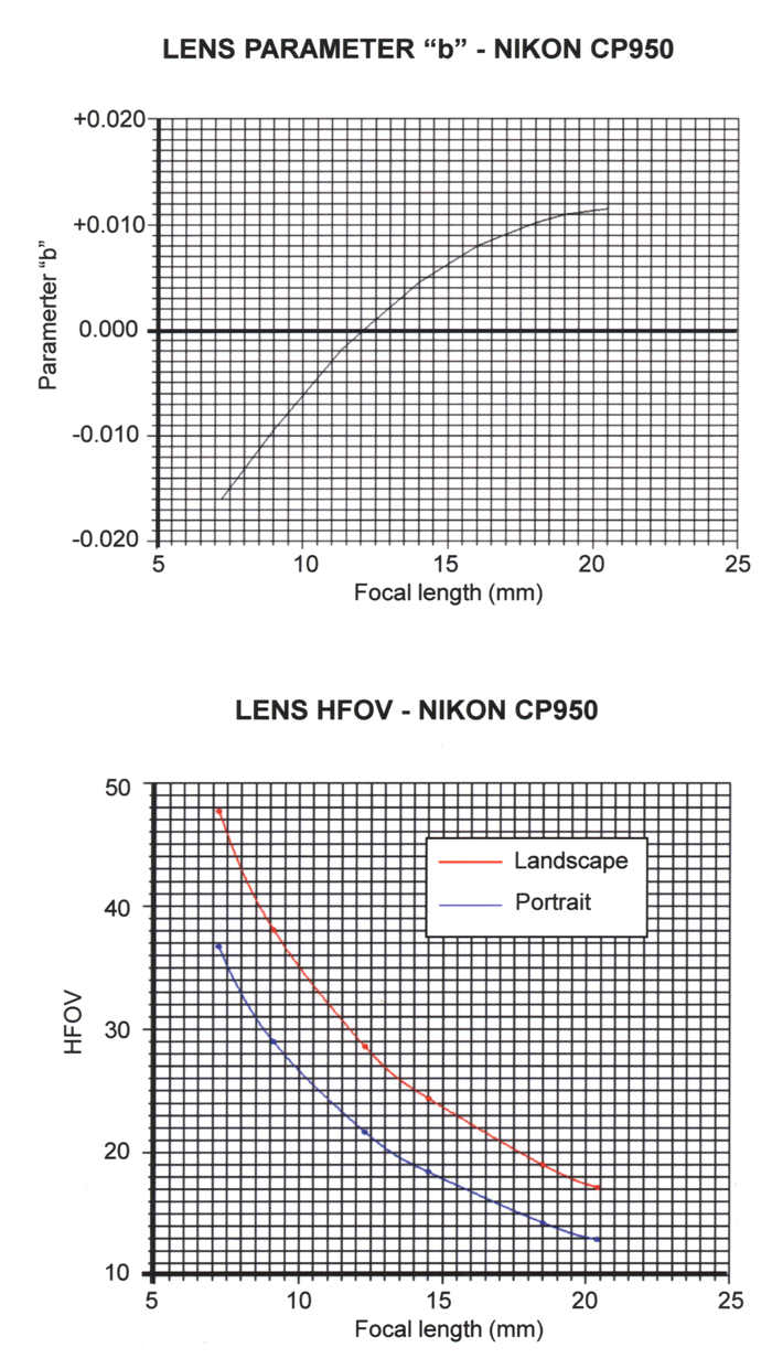
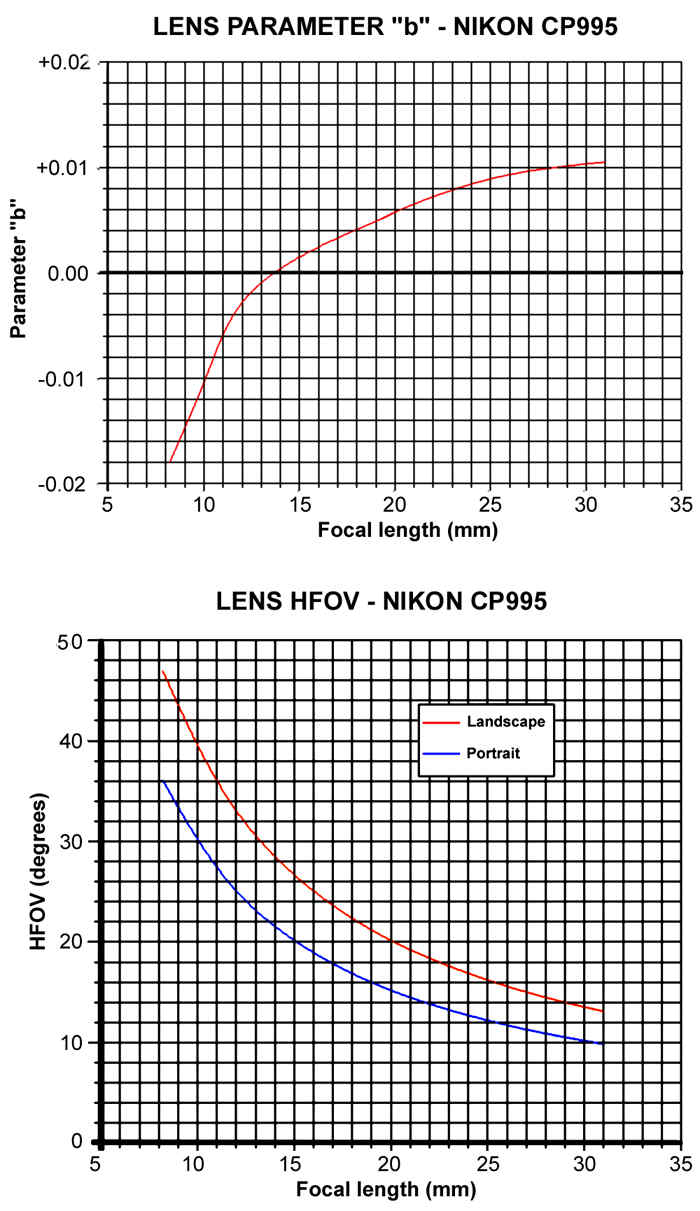
I use these settings for the wide angle zoom setting on my Nikon CP950, but
you will no doubt need a slightly different value of b for your particular lens
and/or zoom setting. Use a positive value of b to correct pin cushion distortion.
To preserve the same image size, set d to a value that makes a+b+c+d=1.
To determine the value of b to use
for your lens, take a picture with a long straight object (such as a door frame
or window frame) near the edge of the picture. Then in Photoshop draw
a line with the measure tool alongside the object to help judge its straightness
in the corrected image. Run the Correct option with above parameters and
see the effect. You can do Undo and then try another value of b, repeating until
satisfied (it doesn't take long) and then save the values for future use.
It is not necessary to keep altering d to match the changing values of b while
you are running the trial settings. Just set d to be 1-b when you have
found the right value of b. You can repeat the procedure for different zoom
settings and plot a graph of b against focal length. Then it is a simple matter
of finding the focal length from the exif data in an image file and then reading
off the correct value of b to use to correct the image. (See sample lens charts
in the links section below).
Once you have a set of lens
parameters that give good correction, then you can enter them directly into
PTGui instead of pre-processing the images, and no further optimization
of those parameters should be needed. NB. Only enter parameters a,b, and c. Parameter d in the Correct plugin
is not the same as the d parameter in PTGui. In PTGui, d and e are shift parameters that are used to correct for off-centre
lenses and image sensors.
MEASURING
HFOV
This is not difficult to do and
should be done for both portrait and landscape orientations at the zoom setting
that you plan to use for panoramas. Take a picture of a metre rule at a distance
of one metre from the lens . Read out the length of rule visible across the
width of the picture. The tangent of half the HFOV is half the visible rule
width in cm divided by 100(cm). Use the scientific option in the Microsoft calculator
to find the angle whose tangent is x, double it to get the HOFV.
E.g. If the width of ruler visible
in the photo is 67cm, half this is 33.5. Divide by 100 gives 0.335. Inverse
tan of this is 18.52 degrees. Double this to give HFOV=37 degrees, near enough.
For a film camera, you should be
able to work out the field of view from the focal length and frame size. Otherwise,
estimate HFOV as best you can. Tip - When you get the hang of things, you can get an accurate
value for HFOV by making a 360 degree panorama and optimizing the HFOV parameter.
PROJECTIONS
For printed panoramas, the choice
is usually between rectilinear and cylindrical projections. In effect, what happens
within the stitcher is that the images are warped and stuck onto an imaginary
spherical surface such that if you look out from the centre of the sphere, you
see exactly what the camera saw. For the projections, you can imagine a lamp
at the centre of the sphere casting an image of the stitched images onto a sheet
of paper. This might be a cylinder of paper wrapped around the sphere and just
touching at its equator (cylindrical projection) or a flat piece of paper just
touching the sphere at one point on the equator (rectilinear projection). In
the latter case, the edges and corners will suffer severe distortion if the
angular field of view of the panorama is too wide (the angle must be less than
180 degrees anyway). The cylindrical projection allows a full 360 degree image
to be generated, but is again liable to distortion on the top and bottom edges
just as for the rectilinear projection.
LINKS
Original Panorama Tools V2.6b1:
http://www.all-in-one.ee/~dersch/
More on correcting
barrel distortion: Barrel Distortions