|
|||||||||
WHAT'S THE OPTIMIZER FOR?First, it should be understood that running the optimizer is not necessarily an essential part of the stitching process. PTStitcher does the actual stitching, and relies upon a script file for getting its instructions on what to do. The script tells it which images to stitch, how they are positioned, and also provides details of the camera lens(es) and their distortion characteristics. If all these parameters are already accurately known, (through the use of calibrated equipment), then the optimizer is not actually needed. In most cases, however, much of this information will be unknown so we use PTOptimizer to work out the missing details as accurately as possible. |
|||||||||
|
|
||||||||
HOW DOES IT ALL WORK THEN?1. Input images are mapped onto a virtual spherical surface, the idea being to position the images so as to recreate the original 360x180 view seen from the camera position, or a part of that view. In addition to the image warping needed to achieve this geometric transformation, the images may also need to be further distorted to correct for barrel/pincushion distortion. 2. The position of each image on the sphere is identified by yaw, pitch and roll values (parameters y,p and r), and the lens distortion correction is controlled by the lens parameters a,b and c. The lens horizontal field of view (HFOV) is a key parameter that enables the size of the remapped image on the spherical surface to be computed. 3. The images are fitted together rather like a jigsaw puzzle. Fix one image and the optimizer will fit all the others around that image to form a composite image. 4. The optimizer works out the optimum position of each image, i.e. the best "fit", within the constraints imposed by the various parameter settings. The control points on matching features in the image overlap areas tell it how images are to be positioned with respect to other images. If the optimizer is given complete freedom to move all images into any position, it will fit the images together very nicely, but the composite image might end up anywhere on the spherical surface. 5. To have some control over where the composite image ends up, you can restrict the position of one or more images in some way. For example, you might set the y,p and r values of the central image of a panorama to 0 degrees. This will ensure that the composite image will be approximately centered in the straight ahead position (where y=p=0 degrees). 6. When a good fit of the images has been established, the composite image needs to be coaxed into a position such that the y,p and r values of the images match those of the camera taking the photographs. When this ideal position has been achieved, the horizon in the image will then be aligned with the pitch=0 line (the equator). Vertical features will be aligned with lines representing equal yaw (lines of longitude). Marking vertical edges and the horizon with t1 and t2 points, respectively, is one way of helping the optimizer to achieve this blissful state of alignment. 7. The stitcher uses the image parameters worked out by the optimizer (or manually specified) to generate the output image by projecting the spherical image in various ways e.g. onto a flat surface (rectilinear) or a cylinder. A portion of the sphere can be output rather than the entire surface, in which case the boundaries of the selection to be output is symmetrically positioned about the yaw=0, pitch=0 point, i.e. the straight ahead view. Thus, this window on the view can be made wider or taller but cannot be shifted up or down or sideways. Of course, the composite image can be shifted on the spherical surface to reveal a different view in the output window. e.g. if you add 10 degrees to the yaw value of every image, the whole panorama will be shifted right by 10 degrees, without affecting the alignment of the images with respect to each other. (Think of a strip of orange peel - the composite image - being slid over the surface of an orange. The strip remains the same shape wherever it is positioned). |
|||||||||
|
|||||||||
SO HOW DO I RUN THE OPTIMIZER? You run the optimizer to achieve two distinct objectives: one is to fit the images together as accurately as possible by aligning the control points; the other is to position the composite image on the virtual spherical surface such that you have the desired view in the output area, usually also aiming to have a flat horizon and upright verticals. In any one run, you should be clear about what you want to achieve and set parameters accordingly. You will generally need to run the optimizer more than once to get the best results, but you can address either or both objectives together in each run. |
|||||||||
|
|||||||||
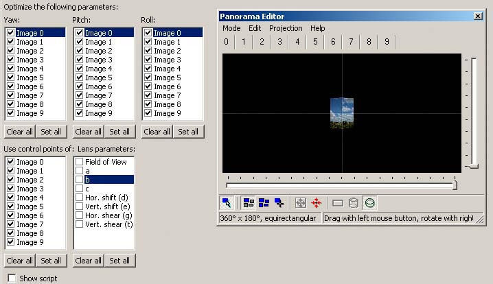
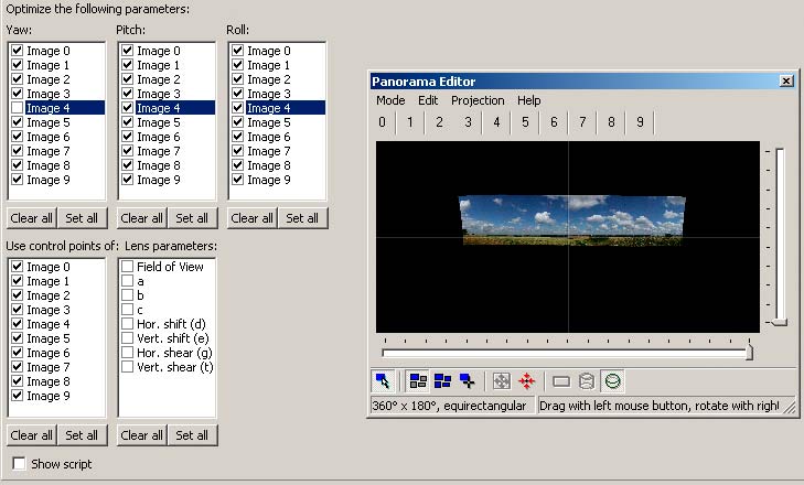
Fitting the images together The optimizer takes the current layout of images as defined in the project file as its starting point and does its best to improve the layout by making changes to the various parameters. It does this in a cyclical fashion, hopefully improving the layout a bit more each time round. Note that you can cancel the optimizer at any time and either accept or reject the current state of the parameters. You control which parameters it is allowed to vary by checking the parameter boxes on the optimizer form provided in PTGui and PTAssembler etc. The output from the optimizer is an updated project file (in memory) containing the new set of parameter values. This then becomes the starting point for the next optimizer run. Everything the optimizer does is aimed at getting the control points into the best alignment possible. How successful it has been is reported at the end of each run, when it will give the average control point alignment error and the maximum error (in pixels). You need to keep an eye on these figures to see how well you are doing. Do remember, though, that these control point distances need to be assessed in relation to the currently specified size of the output image, even though you haven't got around to producing an output image yet. Double the output image size and you will double the average control point distance. So, let's assume you've just assigned your control points. You might now go on to optimize yaw, pitch and roll on all the images, which will allow the optimizer complete freedom to move the images around to get them to align with each other. This is how you would check the boxes (and the 9 images in the project are shown initially stacked up like a pack of cards, all with y=p=r=0 degrees, and in a 360x180 equirectangular projection of the whole sphere, like a map of the world):
(Note: For clarity, I have used the equirectangular projection for the output illustrations in order to represent the complete spherical image space used by the optimizer. In normal use, the projection chosen would be whatever format the ouput was required to be in, and the width of the view would be adjusted to suit the coverage of the images being processed. PTAssembler does not have a continuous preview window like PTGui, so individual previews must be generated as and when required.) |
|||||||||
|
|||||||||
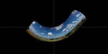
After the optimizer has finished, it reports a good result but the position of the aligned images is not really much like the result we are aiming for: |
|
||||||||
|
|||||||||
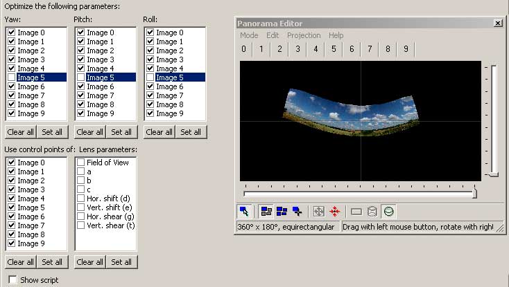
While the average control point distance is a useful indicator of how good a fit of the images has been achieved, this is not the sole measure of the quality of the optimization. Remember that as well as fitting the images together really well, we also want to get the images into a position on the virtual sphere that replicates the original scene. So it is more usual to start off by giving the optimizer a helping hand by assigning rough starting positions to one or more images, which will also speed up the process since the optimizer has less to do. By specifying the initial position of one image, and then not allowing the optimizer to move that image, the optimizer has considerably less room for manoeuvre. It can still align all the images with each other, but the ultimate overall position of the composite image will be determined by the position of the fixed image. So pick an image that you want to be in the middle of the final panorama and fix that by setting its yaw, pitch and roll to 0. Then you can check al lthe optimizer's y,p and r boxes except for the fixed image - the "anchor". The optimizer then produces a result that's somewhat better aligned:
|
|||||||||
|
|
||||||||
The pitch of the anchored image has a direct effect on the flatness of the horizon. This animation shows what happens when the pitch is varied from -5 to +25 degrees: |
|
||||||||
If you happen to know the camera was angled upwards by 15 degrees or so for the anchor image (as in this series of images), you might as well set the initial pitch to 15 instead of 0. It all helps. By doing this, you get this result: Alternatively, with PTAssembler you might set the reference point on the horizon (see below). |
|
||||||||
|
|
||||||||
Generally, rather than optimize everything at once, it is better to optimize only a small number of parameters in each run, and in any case, not more than there are pairs of control points on each seam. So, in the first run, optimize just yaw. Then optimize yaw and pitch on the second run. Then optimize yaw, pitch and roll. This is often quicker than doing everything at once, and the results tend to be better, too. After the images have been sorted into reasonable positions, you can include lens parameter b in the optimizations to correct for barrel distortion in the individual images, which will enable the optimizer to get an even better alignment. This is often all that's required, but some lenses need parameters a and c to be optimized as well in order to get adequate results. Once you have established a good set of lens parameters, it is worth saving them for use in future projects. DO NOT OPTIMIZE THE LENS HFOV PARAMETER unless your project is a 360 degree panorama. Assuming you have put in a reasonably accurate value derived from the focal length setting in the image exif data, there is little or nothing to be gained by optimizing this parameter, and the optimizer may well optimize it down to 0 degrees. But in the case of a 360 panorama, it is ok and indeed desirable to optimize HFOV. The lens shift parameters d and e are not normally optimized when working with rectilinear lenses. They are intended to correct for an off-centre lens and this is more relevant for fish-eye lenses, when it is definitely worthwhile optimizing them. Optimizing d and e can also be useful for "flat stitching" applications, for example as described in Bruno Postle's tutorial. They are specified in units of pixels. |
|||||||||
|
|||||||||
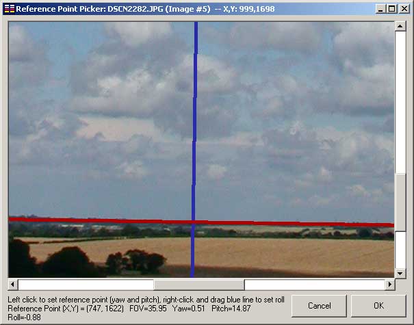
Getting the panorama into the final position with correctly aligned horizontals and verticals Here, we are primarily concerned with relocating the images as a group into a position on the virtual sphere where vertical features become truly vertical, the horizon is horizontal, and the output area contains the view that we want. (Correcting converging verticals will not always be appropriate, but when you do want to correct them, the methods suggested below will be found effective). Realignment of the panorama can be carried out in several ways. Fix one image in position and all the other images will be dragged into their new positions around it in the next run of the optimizer. If you can work out what that position should be, then all well and good. PTAssembler has an option to define a reference point and reference reference image, which enables the horizon to be aligned reasonably accurately. First set the reference image on the Optimizer tab (Step 4) and then click on Set Reference Point. Align the red line with the horizon by following the instructions at the bottom of the panel:
After doing this, you need to optimize with the reference image fixed in position (i.e. y,p and r unchecked), and the other images free to move. There's no need to optimize the lens parameters if you are just wanting to reposition the images. PTGui also provides editing features on its panorama editor window to do a similar job, though maybe less precisely. It does, however, have a nice button that enables you to reposition the images as a group without destroying their "fit". |
|||||||||
|
|||||||||
Using t1 and t2 control points to align the panorama A more accurate method for aligning the panorama is to use the t1 and t2 control point options. The
optimizer will try to bring two features marked by a pair of t1 points into vertical alignment. Similarly, features
marked with t2 points are brought into horizontal alignment. Note that you must only mark features that ought
to be horizontal and vertical as they appear in the output image, which depends on the projection:
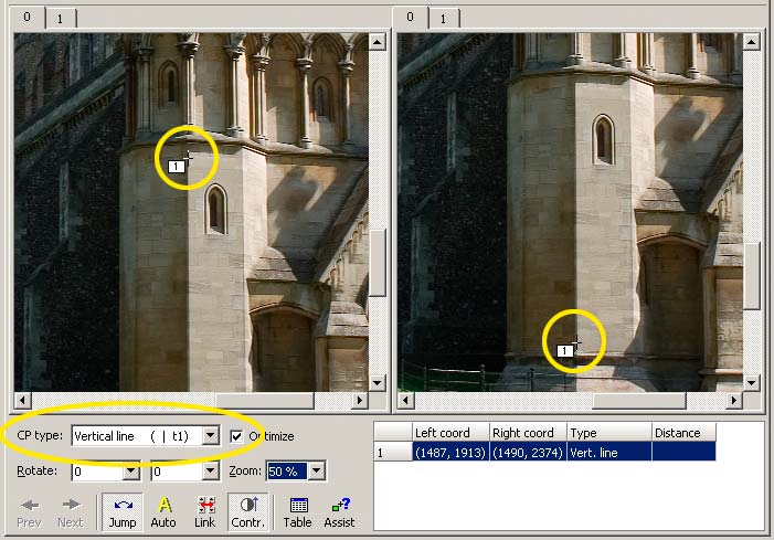
Assign t1 and/or t2 points in addition to the existing control points. Put a pair of t1 points at either end of a vertical feature by setting the first point in one window and the second point in the other window (and note that you can select the same image for display in both windows, if necessary). Reliable features to use for this purpose include the edges of buildings and anything reflected in water. (An object will always be vertically aligned with its reflection in a still pool). Do this for three or four vertical features, if possible. Here's an example (from a different series of images) of a t1 point set on the edge of a wall, using the same image in both windows:
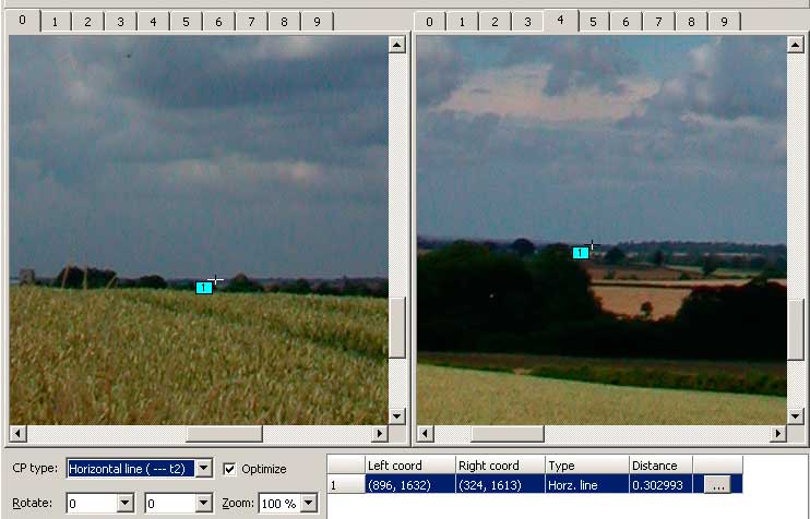
If there is a horizon visible, you can set t2 points on that in a similar way to the t1 points. One pair of t2 points is not enough to give a flat horizon because it may form an arc or wave that just passes through the two points. Use three or four pairs strategically positioned to nail it into position. Alternatively, use one pair of t2 points to get the horizon horizontal and a t3 line to get it straight (see t+ below). Here is the assignment of a single t2 pair on the horizon in images 0 and 4:
|
|||||||||
There's another pair placed at either end of the horizon. After assigning the t1 and t2 points (both can be used together), optimize for y,p and r on all images except for y on one image. Keeping the yaw of one image fixed prevents the panorama shifting sideways. This is how the boxes should be checked:
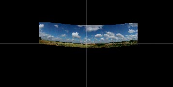
The optimizer will float the whole composite image into a new position as shown here, where the horizon is flat and aligns with the line of pitch=0. Any vertical features will also be standing upright. Remember that if you align the horizon correctly, the verticals will be automatically correct and vice versa. It's easy, really. |
|||||||||
|
|||||||||
Using t3, t4, t5 ... (t+) points for straightening lines These points are placed in pairs along straight line features. The optimizer will try to bring the set of points into a straight line. All the points along the first line defined should be type t3 points. t4 will be used for the next line and so on. The two points of each pair are not placed on identical feaures - just somewhere along the same edge using the two windows in the same manner as for t1 and t2 points. Very important - you must only place these points on lines that should remain straight in the selected output projection. Thus, in a cylindrical projection, only the horizon and verticals are preserved, so don't try to straighten any other lines. Exceptionally, you can cheat a little, and use t+ points on very short sections of otherwise gently curved lines in order to persuade overhead electric wires, for example, to join up neatly at the seams. But only correct very small discontinuities this way. Larger errors should be corrected by editing the output psd layered file. For a rectilinear projection, all straight lines are preserved, so t+ points can be freely used. Useful for calibration purposes to evaluate lens parameters. |
|||||||||
|
|||||||||
Centering the panorama in the output area Centering the panorama horizontally amounts to adjusting the yaw values of all the images by the same amount such that the yaw positions of the two images at either end of the panorama are equally displaced from the yaw=0 point. So if the yaw values of the end images are -60 and +80, subtracting 10 from the yaw values will equalise them at -70 and +70. You could go through the images one-by-one and do this subtraction manually. Or, more conveniently, you can just use the "equalize yaw" button on the PTAssembler Optimizer screen, and it will do all this for you.
Another way is to subtract the10 only from the yaw value of the anchor image and then re-optimize. All the images will then be dragged into alignment with the anchor and the panorama will become centered. PTGui has an image centering button too, but you need to be aware that it centers the image vertically as well. So it's best to use this only early on in the proceedings, otherwise you risk spoiling the vertical positioning perhaps already established to flatten the horizon.
|
|||||||||
|
|||||||||
GENERAL HINTS AND TIPS |
|||||||||
|
|||||||||
Correcting perspective distortion in single images To do this, you carry out exactly the same procedures described for multiple images. In effect, you stitch just one image. Generally, use rectilinear input and output formats unless you are inputting a stitched image for further work, in which case set the lens type appropriate to the projection used (further info below). Set t1 and t2 points as needed and optimize pitch and roll, with yaw fixed when correcting vertical convergence. It may be appropriate to optimize yaw, too, when correcting horizontal convergence. A single image from a panoramic camera should be entered as lens type cylindrical. The FOV will generally be known from the camera specifications. The correct lens type would also need to be specified for an image taken with a fisheye lens when making perspective corrections as part of a "de-fishing" process. |
|||||||||
|
|||||||||
Estimating the position of the horizon If you want to get the perspectives to come out "correctly", it is necessary to align the horizon in the images with the line of pitch=0. This is easy if you have the horizon visible, but more problematical if you don't. Here's a couple of suggestions that might help. 1. If you have a wide expanse of level ground/floor in front of the camera, imagine the camera on its tripod or you holding the camera at some distant point. There might be a doorway, perhaps, to give scale. The imaginary camera will be on a level with the horizon. 2. Along similar lines, if you took the pictures from the shore by a lake or river, again imagine the camera positioned on the distant shore and that will be the position of the horizon, because stretches of water like this are inevitably level. |
|||||||||
|
|||||||||
Picking features for marking with t1 control points It's important to be sure that any "vertical" features that you mark with t1 points really are vertical. Many lamp posts and fence posts are not as upright as they might be. Look at similar features nearby and take care not to pick one that is at odds with all the rest. Objects reflected in water are good sources of perfectly aligned vertical features, e.g. tops of trees are plentiful. However, remember that tree branches wave about in the wind, so it's best to mark the tree top and its reflection in the same image rather than in different images when you have that choice. |
|||||||||
|
|||||||||
Correction of already stitched images You may have a stitched panorama that would benefit from a bit of tweaking to correct an alignment problem. It is quite practical to input that image back into Pano Tools as lens type cylindrical or equirectangular or whatever it happens to be, and carry out any adjustments you like with the optimizer in the same manner as already described for stitching the images in the first place. Just three points to note: 1. For the lens HFOV, enter the value of the panorama FOV that was originally specified for PTStitcher. 2. If the image was cropped to remove the blank areas that you frequently get at top or bottom, extend the image canvas to replace these areas before creating the new project. In other words, you ideally need to re-input the image just as it was originally generated by PTStitcher. |
|||||||||
|
|||||||||
3. Set lens parameters a,b,and c to 0. |
|||||||||
|
|||||||||
|
|||||||||
John Houghton 17/04/06 |
|||||||||
|
|||||||||